Adjustable leveling feet and tube ends


Multi-adjustable pedestal feet to stabilise machinery, equipment & furniture
Keep your equipment sturdy and level with our range of adjustable feet.
Featuring a special insert in the base, our pedestal feet are designed to absorb vibrations, ensuring your machinery stays in place. Whether you need feet for heavy machinery or small appliances, we are bound to have the right solution for you.
Made from mild/stainless steel and reinforced nylon ensures long-lasting durability and performance and resistance to wear-and-tear and/or corrosion. Suitable for use in a wide range of industries including commercial, industrial, workshop, factory or kitchen/food.
Leveling feet styles
Available in the following styles: Ball-joint adjustable feet, bolt-down adjustable feet and fixed adjustable feet.
Knock-in tube ends
To complement our adjustable feet range, we also offer inserts for round or square tubes, which can be turned down to fit heavier wall RHS. Our range of tube ends ensures that you can find the perfect fit for your equipment. The special insert in the base helps to absorb vibration and means your machinery will stay exactly where you put it. Browse our range of knock-in tube ends below.

Features across the range
Available in mild and stainless steel.
Choice of ball joint, bolt-down ball joint or fixed feet.
Made in New Zealand.
10 year warranty.
Specifications
Base |
Glass reinforced nylon – black |
Ball |
Glass reinforced nylon – black |
Pad |
Synthetic Rubber Shore 73 |
Stud |
Mild steel – Plated or Stainless steel |
Nut |
Mild steel – Plated or Stainless steel |
Maximum |
20 degrees |
Ball-joint feet
Adjustable feet allow for variations in floor levels.
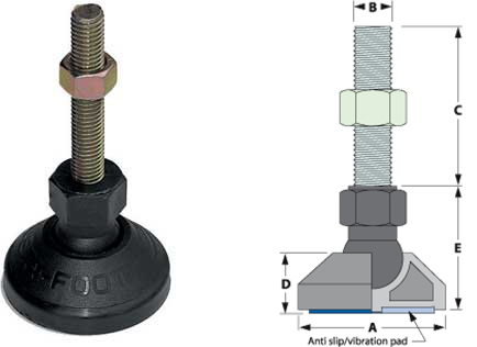
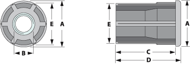
Key
- A = Pad diameter
- B = Thread diameter
- C = Thread length
- D = Pad height
- E = Base height
Specifications
Part No. |
Size |
A |
B |
C |
D |
E |
Load rating |
|
|---|---|---|---|---|---|---|---|---|
| Mild Steel 20 |
Stainless Steel 21 |
|||||||
| AF20/40/ M8/60 |
- |
40 x M8 |
40 |
M8 |
60 |
20 |
33 |
350 |
| AF20/40/ M10/60 |
AF21/40/ M10/60 |
40 x M10 |
40 |
M10 |
60 |
20 |
33 |
500 |
| AF20/60/ M12/65 |
AF21/60/ M12/65 |
60 x M12 |
60 |
M12 |
65 |
20 |
51 |
800 |
| AF20/60/ M16/65 |
AF21/60/ M16/65 |
60 x M16 |
60 |
M16 |
65 |
25 |
51 |
1000 |
| AF20/60/ M16/150 |
- |
60 x M16 |
60 |
M16 |
150 |
25 |
51 |
1000 |
| - |
AF21/60/ M16/165 |
60 x M16 |
60 |
M16 |
165 |
25 |
51 |
1000 |
| AF20/60/ M20/100 |
AF21/60/ M20/100 |
60 x M20 |
60 |
M20 |
100 |
25 |
51 |
1000 |
| AF20/90/ M12/65 |
AF21/90/ M12/65 |
90 x M12 |
90 |
M12 |
65 |
25 |
51 |
1000 |
| AF20/90/ M16/65 |
AF21/90/ M16/65 |
90 x M16 |
90 |
M16 |
65 |
25 |
51 |
1000 |
| AF20/90/ M16/150 |
- |
90 x M16 |
90 |
M16 |
150 |
25 |
51 |
1000 |
| - |
AF21/90/ M16/165 |
90 x M16 |
90 |
M16 |
165 |
25 |
51 |
1000 |
| AF20/90/ M20/100 |
AF21/90/ M20/100 |
90 x M20 |
90 |
M20 |
100 |
25 |
51 |
1000 |
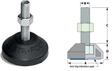
Bolt-down ball joint feet
Bolt-down feet can be fixed to the floor to provide stability.


Key
- A = Pad diameter
- B = Thread diameter
- C = Thread length
- D = Pad height
- E = Base height
Part No. |
Size |
A |
B |
C |
D |
E |
PCD |
Load rating |
|
|---|---|---|---|---|---|---|---|---|---|
Mild Steel 30 |
Stainless Steel 31 |
||||||||
AF30/40/ M8/60* |
- |
40 x M8 |
40 |
M8 |
60 |
20 |
33 |
60 |
350 |
AF30/40/ M10/60* |
AF31/40/ M10/60* |
40 x M10 |
40 |
M10 |
60 |
20 |
33 |
60 |
500 |
AF30/60/ M12/65 |
AF31/60/ M12/65 |
60 x M12 |
60 |
M12 |
65 |
23 |
51 |
80 |
800 |
AF30/60/ M16/150 |
- |
60 x M16 |
60 |
M16 |
150 |
23 |
51 |
80 |
1000 |
AF30/60/ M16/65 |
AF31/60/ M16/65 |
60 x M16 |
60 |
M16 |
65 |
23 |
51 |
80 |
1000 |
- |
AF31/60/ M16/165 |
60 x M16 |
60 |
M16 |
165 |
23 |
51 |
80 |
1000 |
AF30/60/ M20/100 |
AF31/60/ M20/100 |
60 x M20 |
60 |
M20 |
100 |
23 |
51 |
80 |
1000 |
AF30/90/ M12/65 |
AF31/90/ M12/65 |
90 x M12 |
90 |
M12 |
65 |
25 |
51 |
60 |
1000 |
AF30/90/ M16/65 |
AF31/90/ M16/65 |
90 x M16 |
90 |
M16 |
65 |
25 |
51 |
60 |
1000 |
AF30/90/ M16/150 |
- |
90 x M16 |
90 |
M16 |
150 |
25 |
51 |
60 |
1000 |
- |
AF31/90/ M16/165 |
90 x M16 |
90 |
M16 |
165 |
25 |
51 |
60 |
1000 |
AF30/90/ M20/100 |
AF31/90/ M20/100 |
90 x M20 |
90 |
M20 |
100 |
25 |
51 |
60 |
1000 |
Fixed feet
Key
- A = Pad diameter
- B = Thread diameter
- C = Thread length
- D = Pad height
Part No. |
Size |
A |
B |
C |
D |
Load rating |
|
|---|---|---|---|---|---|---|---|
Mild Steel 40 |
Stainless Steel 41 |
||||||
AF40/40/ M8/35 |
AF41/40/ M8/35 |
40 x M8 |
40 |
M8 |
35 |
20 |
350 |
AF40/40/ M10/35 |
AF41/40/ M10/35 |
40 x M10 |
40 |
M10 |
35 |
20 |
500 |
AF40/60/ M12/60 |
AF41/60/ M12/60 |
60 x M12 |
60 |
M12 |
60 |
20 |
800 |
Fixed adjustable leveling screw-in feet
Stainless steel adjustable foot, 90mm pad, M20 x 110mm long thread, 304 grade stainless steel, fixed base.

Order code: |
HDP121/90/M20110 |
Pad diameter: |
90 mm |
Thread diameter: |
M20 |
Thread length: |
110 mm |
Price: |
$70 (ex GST) |
|
|
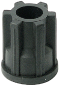
Knock-In Tube Ends for Adjustable Feet
For adjustable feet
Please note: Tube ends are suitable for adjustable feet only, not castors. The internal thread is not long enough to support a thread on a castor – there would be too much 'leverage' inside the tube.
Square knock-in tube ends

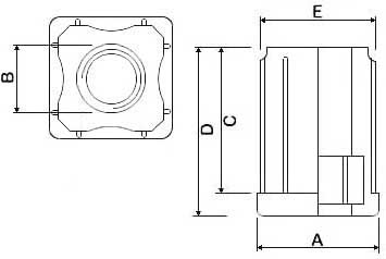
Key:
A = Outside tube (OD)
B = Internal thread
C = Knock-in length
D = Overall length
E = Internal size (ID)
|
Part No. |
Size |
A |
B |
C |
D |
E |
Load rating |
||
|---|---|---|---|---|---|---|---|---|---|
Mild Steel 10 |
Stainless Steel 11 |
||||||||
AF10/25/ M16 |
AF11/25/ M16 |
25 x M16 |
25 |
M16 |
39 |
44 |
22-23 |
250 |
|
AF10/30/ M8 |
AF11/30/ M8 |
30 x M8 |
30 |
M8 |
39 |
45 |
26-27 |
350 |
|
AF10/30/ M10 |
AF11/30/ M10 |
30 x M10 |
30 |
M10 |
39 |
45 |
26-27 |
350 |
|
AF10/30/ M12 |
AF11/30/ M12 |
30 x M12 |
30 |
M12 |
39 |
45 |
26-27 |
350 |
|
AF10/30/ M16 |
AF11/30/ M16 |
30 x M16 |
30 |
M16 |
39 |
45 |
26-27 |
350 |
|
AF10/32/ M8 |
AF11/32/ M8 |
32 x M8 |
32 |
M8 |
39 |
45 |
28-29 |
350 |
|
AF10/32/ M16 |
AF11/32/ M16 |
32 x M16 |
32 |
M16 |
39 |
45 |
28-29 |
350 |
|
AF10/35/ M8 |
AF11/35/ M8 |
35 x M8 |
35 |
M8 |
39 |
45 |
31-32 |
350 |
|
AF10/35/ M10 |
AF11/35 M10 |
35 x M10 |
35 |
M10 |
39 |
45 |
31-32 |
400 |
|
AF10/35/ M12 |
AF11/35/ M12 |
35 x M12 |
35 |
M12 |
39 |
45 |
31-32 |
400 |
|
AF10/35/ M16 |
AF11/35/ M16 |
35 x M16 |
35 |
M16 |
39 |
45 |
31-32 |
400 |
|
AF10/38/ M8 |
AF11/38/ M8 |
38 x M8 |
38 |
M8 |
41 |
45 |
35-36 |
500 |
|
AF10/40/ M16 |
AF11/40/ M16 |
40 x M16 |
40 |
M16 |
39 |
45 |
36-37 |
350 |
|
N/A |
AF11/51/ M20 |
51 x M20 |
51 |
M20 |
39 |
47 |
47-48 |
750 |
|
Round knock-in tube ends
Part No. |
Size |
A |
B |
C |
D |
E |
Tube ID * |
Load rating |
|
|---|---|---|---|---|---|---|---|---|---|
Mild Steel 80 |
Stainless Steel 81 |
||||||||
- |
AF81/25/ M8 |
25 x M8 |
25 |
M8 |
38 |
46.5 |
23 |
22 |
100 |
- |
AF81/25/ M10 |
25 x M10 |
25 |
M10 |
38 |
46.5 |
23 |
22 |
100 |
- |
AF81/25/ M12 |
25 x M12 |
25 |
M12 |
38 |
46.5 |
23 |
22 |
100 |
- |
AF81/32/ M8 |
32 x M8 |
32 |
M8 |
39 |
45 |
29.5 |
28-29 |
200 |
- |
AF81/32/ M10 |
32 x M10 |
32 |
M10 |
39 |
45 |
29.5 |
28-29 |
250 |
- |
AF81/32/ M12 |
32 x M12 |
32 |
M12 |
39 |
45 |
29.5 |
28-29 |
250 |
- |
AF81/32/ M16 |
32 x M16 |
32 |
M16 |
32 |
45 |
29.5 |
28-29 |
250 |
- |
AF81/38/ M10 |
38 x M10 |
38 |
M10 |
38 |
45 |
35.5 |
35-36 |
300 |
- |
AF81/38/ M12 |
38 x M12 |
38 |
M12 |
38 |
45 |
35.5 |
35-36 |
300 |
- |
AF81/38/ M16 |
38 x M16 |
38 |
M16 |
38 |
45 |
35.5 |
35-36 |
300 |
- |
AF81/51/ M12 |
51 x M12 |
51 |
M12 |
38 |
45 |
48 |
47-48 |
450 |
- |
AF81/40/ M10 |
40 x M10 |
40 |
M10 |
39 |
45 |
36.8 |
36-37 |
500 |
- |
AF81/40/ M12 |
40 x M12 |
40 |
M12 |
39 |
45 |
36.8 |
36-37 |
500 |
- |
AF81/40/ M16 |
40 x M16 |
40 |
M16 |
39 |
45 |
36.8 |
36-37 |
500 |
- |
AF81/51/ M12 |
51 x M12 |
51 |
M12 |
38 |
45 |
48 |
47-48 |
450 |
- |
AF81/51/ M16 |
51 x M16 |
51 |
M16 |
38 |
45 |
48 |
47-48 |
450 |
- |
AF81/62/ M16 |
62 x M16 |
62 |
M16 |
38 |
45 |
60.5 |
60-61 |
450 |
Set screws

Specifications
Thread size |
Suits external size tube or SHS |
Order code |
|---|---|---|
12 |
75mm long mild steel set screw |
SPM12X 75SETZ |
12 |
75mm long stainless steel set screw |
SPM12X75SETS |
Browse our latest catalogue